How to choose the right switching transistor for my application? It must withstand the current, generated heat and applied voltages. Current and voltage does not pose any problem. You have to use some calculations about the power dissipation.
For example I need to drive (turn on/off or fade with PWM) 24 Watts of 12 Volt LED stripes from a microcontroller which has I/O output voltage 3.3 V. Best choice is to use some N-channel MOSFET. You don’t need any special MOSFET driver if you are satisfied with slower turn on/turn off times in the magnitude of tens of microseconds.
As an electro-noob I thought that the transistor power rating must be the same or higher as the power required by the load. So I was looking for a transistor that matches. I chose the big ass D2PAK IRF3706S. The maximum ratings table:
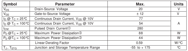
The smallest value with W in the last column is 44 which is almost twice what I need. Good! But not very correct.
Before detailed PD explanation look at the maximum voltages and current: VDS must be at least the value of the power supply which is 12 V. 20 V in the table is fine. VGS range must cover the driving voltage of the microcontroller (0-3.3 V is in the +-12V range). Maximum current ID is 54 A at some high temperature, way higher then 2 A I need. So far no science.
The power and current ratings has always some temperature attached. As you can deduce it is a maximum rating given for that temperature. But sometimes you can see a symbol TC and sometimes TA and sometimes both. TC means controlled temperature of the package. So you somehow ensure (e.g. with a heat sink) that the temperature of the package will not raise above the stated value. If you can cool the IRF3706S to 25°C then you can dissipate even the maximum 88 W. The same with the current. Symbol TA means ambient temperature. No heat sink, just free air flow with that temperature.
The IRF3706S datasheet does not contain power and current values for ambient temperatures but don’t worry, you can get it. You need a thermal resistance table with a junction to ambient value:
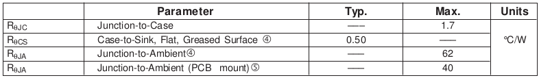
Let’s say I need to calculate maximum power dissipation without a special heat sink. I’m able to keep the air temperature TA at 35°C and the package’s built-in heat sink is PCB mounted. The equation for that is:
[latex]P_D = \frac{\textrm{max}(T_J) – T_A}{R_{\Theta{}JA}} =\frac{175 – 35}{40} = 3.5 W[/latex]
Whaaa? Without a heat sink and a ventilator this D2PAK monster can withstand only 3.5 Watts of power dissipation? Disappointment. But at the end it will be enough because the transistor’s maximum power dissipation has almost nothing to do with the driven load!
Finally to the correct perspective of view. First let’s rename the term power dissipation to power loss. This might start to make sense. Power loss is caused by the transistor’s (or any other part) internal resistance and flowing current (P = R * I2) and it makes the transistor hot. If the N-MOSFET gate is grounded (or below the ground) then the internal resistance is extremely high and no current is flowing. Interesting stuff happens when there is a positive voltage on the gate pin. MOSFET is never fully “opened” no matter how high voltage you apply to the gate. It has always some drain-source resistance marked as RDS.
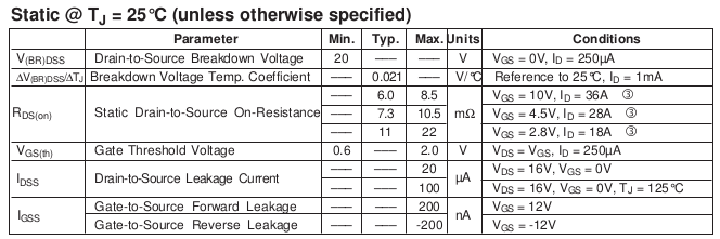
You can see three resistance ranges for three gate voltages. The MCU I/O “on state” is 3.3 V so I will take the worst scenario of VGS = 2.8 V and max(RDS) = 22 mOhm. That makes the maximum power loss in my case:
[latex]P_D = R_{DS} \cdot I^2 = 0.022 \cdot 2^2 = 0.088 W[/latex]
See? This is the maximum power loss/dissipation on the transistor when driving 24 W of LED stripes. It leads to a conclusion that it is definitely not necessary to use such big transistor and even a tiny SOT-23 can do the work. E.g. TSM2314CX can easily drive the LEDs without any significant heating.
MCU note: always place a resistor between MCU and the MOSFET gate. MOSFETs have large gate impedance but also some not negligible capacitance. During the transistor switching time there is a little current flow. Especially when you do PWM at higher frequencies. I’ve burned my first BeagleBone Black this way. This board is a great thing but also very sensitive. I/O current is rated at maximum of 5 mA so 1 k resistor will suffice.
No Comments
No comments yet.
RSS feed for comments on this post.
Sorry, the comment form is closed at this time.