Turning circuits on and off by a toggle switch is so old school. Today devices have a single push button and that button can power up or down the device with a single push without much force applied.
Dave Jones has an excellent tutorial for this topic designing a soft latching turn on/off button on his EEVBlog. This solution is not bad because it does not drain any current when the device is off but it has problems with capacitive loads.
Following solution is a compilation of a very common single push on-push off circuit with a 555 timer. You can find variations all over the internet. There are two major advantages:
- It can drive capacitive/inductive loads.
- Delay between switching – your device will not be damaged by quick switching on-off-on-off… Kids like to do that. If you turn it on then you have to wait few hundreds of milliseconds to be able to turn if off and vice versa.
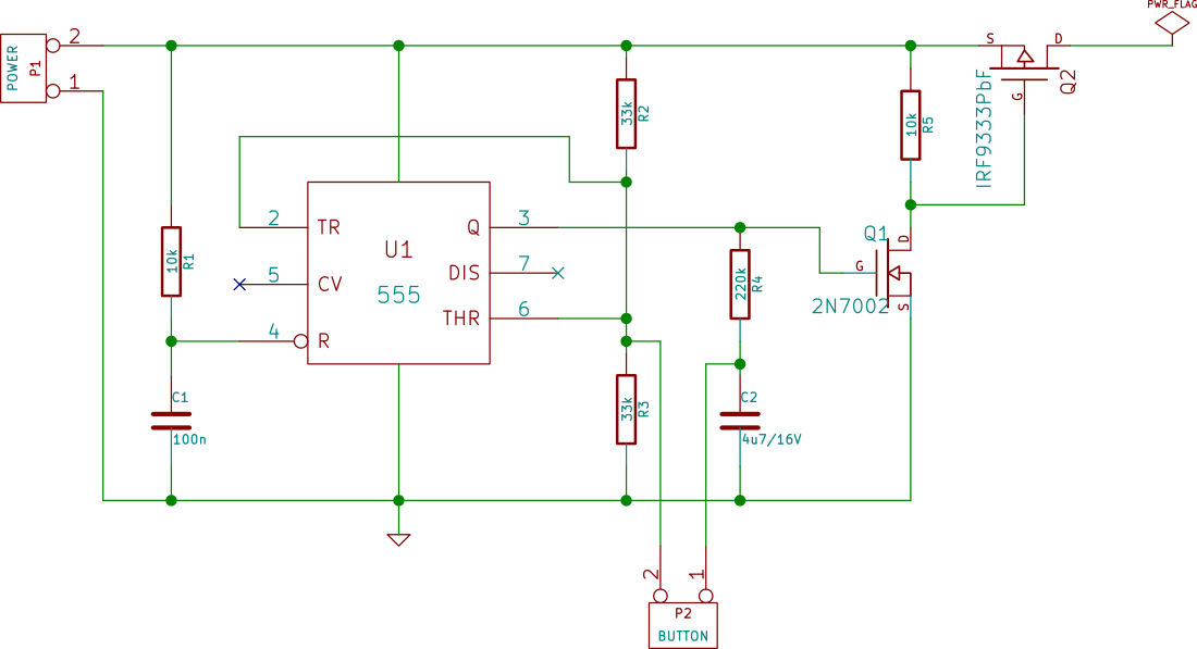
This circuit is designed to operate on 12 V power supply. With a few modifications it can be altered for almost any voltage. Switching transistor is a P-MOSFET IRF9333 which has a very low RDS(on) = 19 mOhm (thus low voltage drop) and can deliver current up to 9 A. It can be replaced by any P-MOSFET of course.
Pair R1 and C1 ensures that the 555 timer will be in a defined state after you connect the device to a power supply. You don’t want your device to start by itself when you plug it in. C2 and R4 provide the necessary delay between switching. Values in the schematic are chosen for approx. 0.5 second delay. Q1 is a logic level invertor.
It drains some small current even if the device is turned off. The drain is caused by the resistors R2 and R3 (0.18 mA @ 12 V) and the supply current of the 555 timer (max. 15 mA for a bipolar version, 0.2 mA for a CMOS).
Hi
I have tested this circuit in simulator.in simulator the voltage out put of Q1 is varying as i press sw, but Q2 output remain same.
Comment by Taher — 2014-09-05 @ 16:34
Hi! What load do you have behind the Q2?
Comment by admin — 2014-09-05 @ 16:46
I have few devices built with this circuit and they work fine.
Comment by admin — 2014-09-07 @ 14:49